

Product Specifications
|
PRODUCT TYPE LED Signal Bulbs |
SOCKET TYPE 1156 |
|
MODEL NO. P-S09-1156-150°-W-NP-U P-S09-1156-150°-Y-NP-U P-S09-1156-150°-R-NP-U P-S09-1156-180°-W-NP-U P-S09-1156-180°-Y-NP-U P-S09-1156-180°-R-NP-U |
LIGHT COLOR White / Yellow / Red |
|
LED TYPE 3020 SMD |
LED QUANTITY 16 LEDs |
|
OPERATING VOLTAGE DC 9–18V |
CURRENT TEST VOLTAGE 13.5V |
|
APPLICATIONS Back-Up / Rear Fog Lights, Depending on Color and Vehicle Fitment |
PIN ANGLE OPTIONS 150° / 180° |
|
INITIAL INPUT CURRENT 2.4 A ± 10% |
STABLE INPUT CURRENT 2.0 A ± 10% |
|
WHITE INITIAL LUMINOUS FLUX 2,200 lm ± 10% |
WHITE STABLE LUMINOUS FLUX 1,700 lm ± 10% |
|
YELLOW INITIAL LUMINOUS FLUX 1,520 lm ± 10% |
YELLOW STABLE LUMINOUS FLUX 1,100 lm ± 10% |
|
RED INITIAL LUMINOUS FLUX 350 lm ± 10% |
RED STABLE LUMINOUS FLUX 270 lm ± 10% |

S09 Series 1156 LED Signal Bulbs with 150° or 180° Pins
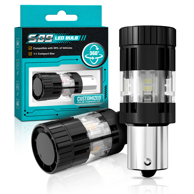
The CN360 S09 Series 1156 combines sixteen 3020 SMD LEDs with a choice of 150° or 180° locating-pin configurations. Both base options are available in white, yellow, and red. Listed applications include back-up and rear fog lighting where the color, socket, and vehicle circuit are compatible.
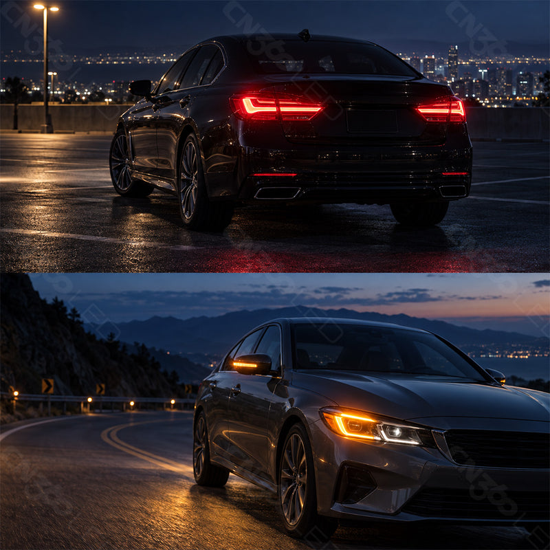
Signal Lighting for Compatible Rear Lamps
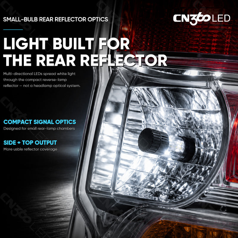
The 1156 range lists back-up and rear fog lighting as its intended applications where the original bulb holder and circuit are compatible. The light color must match the lamp's function and lens. A shared socket designation identifies the connection format, while the complete lamp assembly determines the appropriate use.
Consider the reflector, lens, and available space together when selecting the bulb. These parts influence the distribution and appearance of the light after installation. The specified lumen value describes bulb output, while the finished lamp pattern depends on the complete assembly.

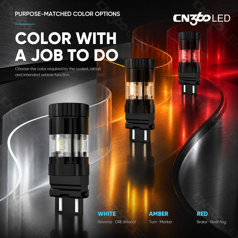
White, Yellow, and Red Light Options
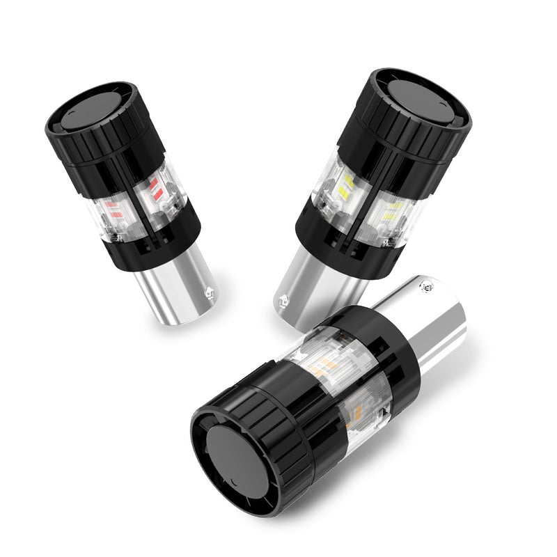
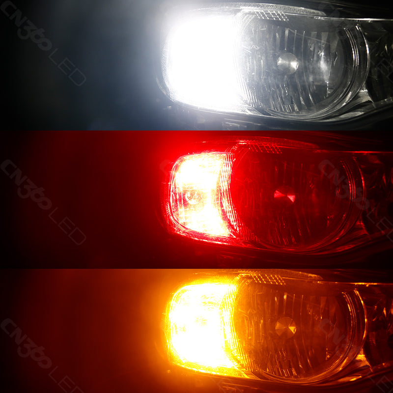
White, yellow, and red versions are available with either locating-pin configuration. Each bulb is selected for its required color; these options do not indicate automatic color switching. The choice should follow the original lamp function, lens color, and the lighting requirements of the intended vehicle position.

Use the output figures for the selected color when evaluating the bulb. The appearance of white, yellow, and red light through a vehicle lens differs, so the color choice and the light-output rating should be considered together. Confirm the installed result within the intended housing.


16 LED Lighting Configuration
The 1156 configuration uses 16 leds with 3020 SMD light sources. This arrangement forms the lighting section of the bulb and should be matched to the corresponding socket version. The LED specification identifies the light-source configuration without assigning an unsupported chip brand.
The LED assembly works with the lamp's existing optical surfaces to deliver light through the lens. Correct bulb seating maintains the intended position inside the housing. Check the space around the complete lighting head and ensure that the lens or rear cover can be fitted normally after replacement.
Initial and Stable Light Output
White output is 2,200 lm ± 10% initially and 1,700 lm ± 10% when stable. Yellow output is 1,520 lm ± 10% initially and 1,100 lm ± 10% when stable. Red output is 350 lm ± 10% initially and 270 lm ± 10% when stable.
Initial and stable output describe different operating states of the selected bulb. They are not two selectable brightness settings. Use the corresponding current and light-output values together when assessing this version, and keep the color-specific specification associated with the correct bulb.

Electrical Specifications at 13.5V
Input current is specified at 2.4 A ± 10% initially and 2.0 A ± 10% when stable, measured at 13.5V. These electrical values apply to the listed color options in both pin-angle configurations. Match the bulb to a compatible lamp circuit within its DC 9–18V operating range.
The specified test voltage identifies the condition used for the current values. The operating range describes the supply range for this version. Matching both the socket and electrical requirements helps establish suitability for the intended installation.

150° and 180° Locating-Pin Options
The 150° and 180° options refer to the angular spacing of the two locating pins on the sides of the base. They describe the mechanical connection, not the beam angle. Both pin arrangements are available in all three colors, giving six combinations within the 1156 range.
Match the original pin arrangement before selecting the color. The bulb should seat in the appropriate holder without forcing the locating pins. Once fitted, check normal operation through the vehicle's controls and verify the appearance of the light in the intended lamp assembly.